For A 5kw Dc Motor The Number Of Slots Per Pole Should Be
- For A 5kw Dc Motor The Number Of Slots Per Pole Should Be Paid
- For A 5kw Dc Motor The Number Of Slots Per Pole Should Bet
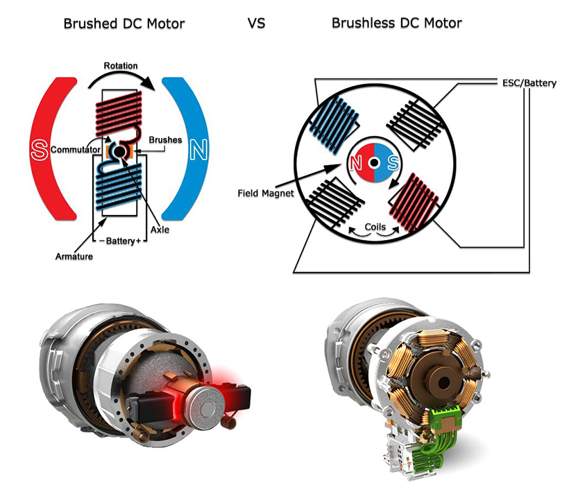
The ratio of poles to slots changes the 'gearing' of the motor. If you assume that all of the motors are basically the same size, then. When the pole/slot ratio is a lower value 4/12= 1/3, the motor will have a higher KV for the same # of turns around each tooth than a motor with a 6/12 = 1/2 ratio, or a 6/9= 2/3. We can see that each phase’s pole is divided into two coils which are equal to two solts/pole/phase, Hence, when you are allowed to have 24 turns/phase you will have 24 turns divided into two poles which are 12 turns /pole and 6 turns/slot. If you would please share your FEMM model with us that would be great!
Basically armature winding of a DC machine is wound by one of the two methods, lap winding or wave winding. The difference between these two is merely due to the end connections and commutator connections of the conductor. To know how armature winding is done, it is essential to know the following terminologies -
- Pole pitch: It is defined as number of armature slots per pole. For example, if there are 36 conductors and 4 poles, then the pole pitch is 36/4=9.
- Coil span or coil pitch (Ys): It is the distance between the two sides of a coil measured in terms of armature slots.
- Front pitch (Yf): It is the distance, in terms of armature conductors, between the second conductor of one coil and the first conductor of the next coil. OR it is the distance between two coil sides that are connected to the same commutator segment.
- Back pitch (Yb): The distance by which a coil advances on the back of the armature is called as back pitch of the coil. It is measured in terms of armature conductors.
- Resultant pitch (Yr): The distance, in terms of armature conductor, between the beginning of one coil and the beginning of the next coil is called as resultant pitch of the coil.

Armature winding can be done as single layer or double layer. It may be simplex, duplex or multiplex, and this multiplicity increases the number of parallel paths.
[Also read: Armature reaction in DC machines]
For A 5kw Dc Motor The Number Of Slots Per Pole Should Be Paid
Lap winding and Wave winding


In lap winding, the successive coils overlap each other. In a simplex lap winding, the two ends of a coil are connected to adjacent commutator segments. The winding may be progressive or retrogressive. A progressive winding progresses in the direction in which the coil is wound. The opposite way is retrogressive. The following image shows progressive simplex lap winding.
In wave winding, a conductor under one pole is connected at the back to a conductor which occupies an almost corresponding position under the next pole which is of opposite polarity. In other words, all the coils which carry emf in the same direction are connected in series. The following diagram shows a part of simplex wave winding.